|
|
|
 Home
> Clean room > Clean Room Specification
|
| |
|
|
 |
| |
|  
|
| |
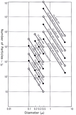
Outline of Fed. Std. 209E
|

The highest value of a class is the name of
the class.
The highest value is expressed with a concentration
more than specified
(Number of Particles per Unit Volume).
|


|
| Item |
Description |
| Unit |
Primarily the metric system is used and
UK units are used in combination. |
| Class
Expression |
The number of particles of 0.5§ or larger
is defined with 10/§© and X is used for the mark of class.
¡®M¡¯ is added to clearly represent the mark of the metric
system. |
| Class
Classification |
Class M1 with higher level of cleanliness
than that of 209D Class 1 and Class M7 with lower level
of cleanliness than that of Class 100,000 were added. |
| Particle
Instrumentation |
CNC can be used in instrumentation and the
diameter of a particle instrumented can be 0.02§ or larger.
In that case, Class U(X) is marked.
U = Mark of Particle Instrumentation
X = Maximum Particle Concentration (P/§©) |
| Standard
Measurement Particle |
It can be 0.1, 0.2, 0.3, 0.5 or 5 micron
but other diameters may be used. |
| Sampling |
Other sampling flows may be used in instrumentation
depending on the location of instrumentation but the particle
concentration must be expressed as ¡®number/unit volume.¡¯
If the number of sampling points is 10 or more, then a
simple average may be used. If the level of cleanliness
is higher than Class M2.5, a continuous sampling may be
allowed for reducing the instrumentation time. |
| Annex |
Standards and terms related to 209D are
deleted but the uniform velocity suctioning, super-fine
particle concentration measurement and continuous sampling,
for higher level of cleanliness than Class M2.5, are added. |
|


|
| |
| Class
Mark
|
Class Highest
Value |
| 0.1§
|
0.2§
|
0.3§
|
0.5§
|
5§
|
| Unit
Volume |
Unit
Volume |
Unit
Volume |
Unit
Volume |
Unit
Volume |
| Meter
System
|
UK
Unit |
(§©)
|
(ft©ø)
|
(§©)
|
(ft©ø)
|
(§©)
|
(ft©ø)
|
(§©)
|
(ft©ø)
|
(§©)
|
(ft©ø)
|
| M1
|
- |
350 |
9.91 |
75.7 |
2.14 |
30.9 |
0.875 |
10.0 |
0.283 |
- |
- |
| M1.5
|
1 |
1,240 |
35.0 |
265 |
7.50 |
106 |
3.00 |
35.3 |
1.00 |
- |
- |
| M2 |
- |
3,500 |
99.1 |
757 |
21.4 |
309 |
8.75 |
100 |
2.83 |
- |
- |
| M2.5 |
10 |
12,400 |
350 |
2,650 |
75.0 |
1,060 |
30.0 |
353 |
10.0 |
- |
- |
| M3 |
- |
35,000 |
991 |
7,570 |
214 |
3,090 |
87.5 |
1,000 |
28.3 |
- |
- |
| M3.5 |
100 |
- |
- |
26,500 |
750 |
10,600 |
300 |
3,530 |
100 |
- |
- |
| M4 |
- |
- |
- |
75,700 |
2,140 |
30,900 |
875 |
10,000 |
283 |
- |
- |
| M4.5 |
1,000 |
- |
- |
- |
- |
- |
- |
35,300 |
1,000 |
247 |
7.00 |
| M5 |
- |
- |
- |
- |
- |
- |
- |
100,000 |
2,830 |
618 |
17.5 |
| M5.5 |
10,000 |
- |
- |
- |
- |
- |
- |
353,000 |
10,000 |
2,470 |
70.0 |
| M6 |
- |
- |
- |
- |
- |
- |
- |
1,000,000 |
28,300 |
6,180 |
175 |
| M6.5 |
100,000 |
- |
- |
- |
- |
- |
- |
3,530,000 |
100,000 |
24,700 |
700 |
| M7 |
- |
- |
- |
- |
- |
- |
- |
10,000,000 |
283,000 |
61,800 |
1,750 |
|
  |
| |
These represent the general rule about the selection of the air
current velocity in a clean room.
The air current velocity is specified as (1) average velocity (m/s
or ft/m) or (2) the number of ventilation per hour (number / hour).


| Class |
Air Current Type |
Average
Air Current Velocity 1 |
Ventilations
per Hour 2 |
M7&M6.5(Class 100,000) |
NM |
.005- .041m/sec (1-8ft/min) |
5 - 48 |
M6&M5.5(Class 10,000) |
NM |
.051- .076m/sec (10-15ft/min) |
60 - 90 |
M5&M4.5(Class 1,000) |
NM |
.127- .203m/sec (20-40ft/min) |
150 - 240 |
M4&M3.5(Class 100) |
UNM |
.203- .406m/sec (40-80ft/min) |
240 - 480 |
M3&M2.5(Class 10) |
U |
.254- .457m/sec (50-90ft/min) |
300 - 540 |
M2&M1.5(Class 1) |
U |
.305- .457m/sec (60-90ft/min) |
360 - 540 |
M1 Cleaner |
U |
.305- .508m/sec (60-100ft/min) |
360 - 600 |
(U=Unitary Direction, N=Non-Single Direction, M=Mixed)
1. The average velocity is generally used for unitary direction.
2. The number of ventilation per hour can be determined by the following
expression:
| Ventilations per Hour [number/hr]
= |
Average Air Current Velocity
(m/sec)¡¿Shot Area (m2)¡¿3,600sec |
|
| Indoor Volume (m3) |
|
  |
| |

|
  |
| |
| Item |
Description |
| Entry&Exit |
- Minimize and separately consider Entry and Exit. (Especially
for the installation of air shower)
- Do not expose them directly to the air (Air Lock Room)
- Locate them downstream (Especially, Cross Floor).
|
| Locker Room |
- Take as much as air for the locker room.
- Install a washstand and prepare drinks if many peoples
gather.
- Install at least the double door between clean rooms.
(Install Air Shower Systems)
- Enable internal communications.
- Establish a rest room, if necessary.
|
| Take In & Out |
- Use a pass box if applicable (parts).
- Attach a take-in hole. (Large Systems)
|
| Indoor Arrangement |
- Simplify.
- Install the control office outdoor. Consider how to contact.
- Plan to expand.
- Minimize the movement.
- Consider the direction of fresh air current to arrange
workplace.
- In works causing oscillation, use partitions, local exhaust
and return duct.
|
| Indoor Facilities |
- Minimize the exposure of wire and duct.
- Install the light system over the ceiling if applicable.
- Prepare for emergency, fire, blackout or poisonous gas.
- Install an inter-phone or telephone.
- Clean.
- Record particles concentration, temperature and humidity.
|
|

|
